VIC™
PIC® Microcontroller programming made easy
Created by Vikas N Kumar / Selective Intellect
Follow us on Twitter at @_vicash_ / @selectintellect
© 2014-2015. Selective Intellect LLC. All Rights Reserved.
What is VIC™ ?
VIC™ is an easy to use domain specific language to develop firmware for Microchip's PIC® microcontroller units (MCU).
Why Should You Use VIC™ ?
If you ...
- like to use Microchip PIC® MCUs
- do not like coding in C or assembly or BASIC
- would like to understand what your code is doing months from now
- want portability between various MCUs
- want to simulate your code in PIC® simulators easily
- like scripting language constructs and paradigms
... then VIC™ is for you !
Why We Designed VIC™ ?
Press the space bar to navigate if using the keyboard.
The Reasons
As we did more PIC® microcontroller projects, we found that ...
- writing boiler plate code was tedious and boring
- using PICBASIC® or Microchip’s C compilers was not fun
- portability of code across MCUs was difficult, annoying, time consuming and prone to error
- copy-pasting code between projects led to library creation which led to subtle maintenance problems over time
... so we decided to automate all of these problems away !
A Domain Specific Language
To automate our problems away we wanted a DSL that did the following for us:
- exemplify the Do What I Mean (DWIM) philosophy
- be easy to understand months later
- auto-generate efficient PIC® assembly for the selected MCU
- be extremely portable between various MCUs
- automatically find incompatibilities between MCU functionality and the code being compiled
Some More Desires
- reduce the need for reading data sheets all the time
- integrate with existing debuggers and simulators
- generate boiler plate code appropriately as needed for the selected MCU
- automate high level functions such as UART, I2C, SPI, switch debouncing, interrupt handling, etc.
And Most Important of All
We wanted a capability to auto-generate the DSL from higher level languages like Perl or Python or from flowcharts
Thus VIC™ was born !
Press the space bar to navigate if using the keyboard.
License
VIC™ is dual-licensed under the
- Perl Artistic License
- GNU General Public License v3
Hello World!
Let's say we want to light up an LED.
Let's use the P16F690 PIC® microcontroller chip.
Let's assume the pin RC0 is connected to an
LED.
PIC® P16F690
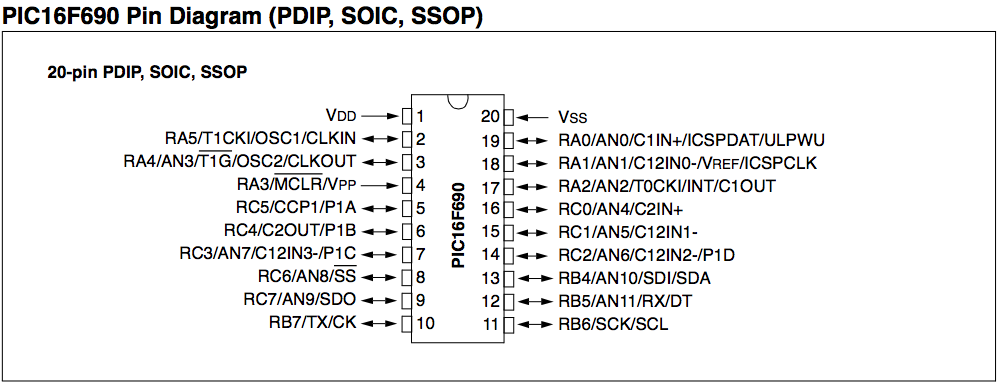
Click to enlarge the picture
... or ...
$ vic --chip-pinout P16F690
                             +======__======+
                      Vdd ---|1           20|--- Vss
                             |              |
     RA5/T1CKI/OSC1/CLKIN ---|2           19|--- RA0/AN0/C1N+/ICSPDAT/ULPWU
                             |              |
  RA4/AN3/T1G/OSC2/CLKOUT ---|3           18|--- RA1/AN1/C12IN0-/Vref/ICSPCLK
                             |              |
             RA3/MCLR/Vpp ---|4           17|--- RA2/AN2/T0CKI/INT/C1OUT
                             |              |
             RC5/CCP1/P1A ---|5           16|--- RC0/AN4/C2IN+
                             |              |
                             |   P16F690    |
                             |              |
            RC4/C2OUT/P1B ---|6           15|--- RC1/AN5/C12IN1-
                             |              |
      RC3/AN7/C12IN3-/P1C ---|7           14|--- RC2/AN6/C12IN2-/P1D
                             |              |
               RC6/AN8/SS ---|8           13|--- RB4/AN10/SDI/SDA
                             |              |
              RC7/AN9/SDO ---|9           12|--- RB5/AN11/RX/DT
                             |              |
                RB7/TX/CK ---|10          11|--- RB6/SCK/SCL
                             |              |
                             +==============+
Looking at the code
PIC P16F690;

Main {
    digital_output RC0; # mark pin RC0 as output
    write RC0, 0x1; # write the value 1 to RC0
}
Assembly Code You May Have Written
#include <p16f690.inc>
__config (_INTRC_OSC_NOCLKOUT & _WDT_OFF & _PWRTE_OFF & _MCLRE_OFF
            & _CP_OFF & _BOR_OFF & _IESO_OFF & _FCMEN_OFF)
org 0
_start:
    ;; turn on pin RC0 as output
     banksel   TRISC
     bcf       TRISC, TRISC0
     banksel   ANSEL
     bcf       ANSEL, ANS4
     banksel   PORTC
     bcf       PORTC, 0
    ;; write 1 to RC0
     bsf       PORTC, 0
     goto      $
     end
Let's See It Work
Simulating in Software
Using gpsim
as default simulator
PIC P16F690;

Main {
    digital_output RC0; # mark pin RC0 as output
    write RC0, 0x1; # write the value 1 to RC0
}
Simulator {
    attach_led RC0; # attach an LED to the pin RC0
    stop_after 1s; # stop the simulation after 1 second
}
Let's See It Work
Blinking the LED
PIC P16F690;

Main {
     digital_output RC0; # mark pin RC0 as output
     Loop {
         write RC0, 1; # turn the LED on
         delay 1s; # wait 1 second
         write RC0, 0; # turn the LED off
         delay 1s; # wait 1 second
     }
}

Simulator {
    attach_led RC0; # attach an LED to the pin RC0
    stop_after 5s; # stop the simulation after 5 seconds
}
Let's See It Work
Syntax
Typical Program
PIC pic_name; #required

pragma pragma_type pragma_values; # optional

Main {
    # user invokes functions
    function_name argument, argument, argument, ..., argument;
    ...
    ## optional loops
    Loop {
        function_name argument, argument, ..., argument;
        ...
    }
}
## optional simulator block
Simulator {
    # special simulator functions
    function_name argument, argument, argument, ..., argument;
    function_name argument, argument, argument, ..., argument;
}
Typical Program
- Starts with a header naming the chip to compile for
- Every statement ends with a
; - A
Mainblock is required - Pragmas for controlling code generation
- Comments begin with
# - Arithmetic, Bitwise and Logical Operations
Everything is a Block {}
- Unconditional loops:
Loop {} - C-style conditional loops & blocks:
if-else, while - Nested blocks allowed
- User must use built-in functions
Simulatorblock is optional.Actionblocks (callbacks)
Variables, Constants
- Variables begin with a
$sign - String literals enclosed in quotes
- Numeric literals
- Integers only
- Floating point supported only in
Simulatorblock - Units of time, frequency, percentage
$my_timer = 1s; # 1 second $my_timer = 100ms; # 100 milliseconds $frequency = 4kHz; # 4000 Hz $dutycycle = 10%; # 0.01 - Constant Arrays supported as lookup tables
- Pin constants supported as shown in pin diagram
Action Blocks
- Built-in functions allow for callbacks
function_name argument, ..., Action {
    # .. do something here ...
};
debounce RA3, Action {
    # .. do something here ..
}
timer_enable TMR0, 4kHz, ISR {
    # .. do something ..
};
Operations
- Arithmetic operators:
+,-,*,/,% - Assignment operators:
=,+=,-=,*=,/=,%=,^=,|=,&=,<<=,>>= - Bitwise operators:
>>,<<,^,&,| - Complement operators:
!,~ - Logical operators:
<,>,<=,>=,!=,==,&&,|| - Increment/decrement operators:
++,--
Compiler Features
Using commandline options you can:- check if a chip is supported
- list features of a chip
- draw pin diagram on screen
- invoke simulator to test code
- assemble to
.hex - generate intermediate code and parse tree for debugging
Built-in Functions
I/O
- Pin declarations:
digital_outputdigital_inputanalog_input
writedebounce
Timers and Delays
timer_enabletimer_disabledelaydelay_sdelay_msdelay_us
Others
- Mathematical:
sqrt, ror, rol - Pulse Width Modulation
- Analog-to-Digital Converter
- UART/SPI/I2C: Coming Soon!
Simulator
gpsimis the default- Can test code and timing issues
- Can do wave simulations
gpsimsupports 100+ chips- VIC™ generates internal
gpsimlanguage
Delay Function Testing
PIC P16F690;

Main {
    delay 100ms;
    sim_assert "*** EARLY STOP ***";
}

Simulator {
    stopwatch 100ms;
}