VIC™ - A compiler for Microchip’s PIC® Microcontrollers
Project sponsored by Selective Intellect Hosted on GitHub Pages — Theme by mattgraham
Table of Contents Prev Next
Getting Started With VIC™
Writing VIC™ code is similar to writing Bash scripts except for the fact that there are no functions supported as of version 0.23.
For more details on the syntax and features of VIC™ visit the syntax page after you have completed this chapter.
To get you quickly started, here is a quick description of the syntax:
- there is a Main block that is required
- there is a Simulator block that is optional but you can use it to simulate the
generated PIC® assembly code in a supported simulator like
gpsim - code generation properties can be manipulated by pragmas
- the PIC® MCU selected can be defined by a single line header
- blocks are defined using braces
{} - statements end with a semi-colon
; - indentation is personal choice and not a forced choice like that of Python
- you can have multiple statements on a single line if you want
- you can make the code highly readable and follow a set logic
- you can get VIC™ code to visually match the logic of a flowchart
- you can use VIC™ as an intermediate language and write even higher level code in your favorite language like Perl, Python or Ruby and generate VIC™ code from it.
Let us begin with the Hello World! program for the MCU world, which is lighting up an LED.
Hello World! - Lighting up an LED
This example is available in the file share/examples/helloworld.vic and also
on the examples chapter.
Let us select the PIC® MCU P16F690 that comes with the PICKit™ 2 Starter Kit from Microchip. From the data sheet of this MCU, we can see the following pin configuration:
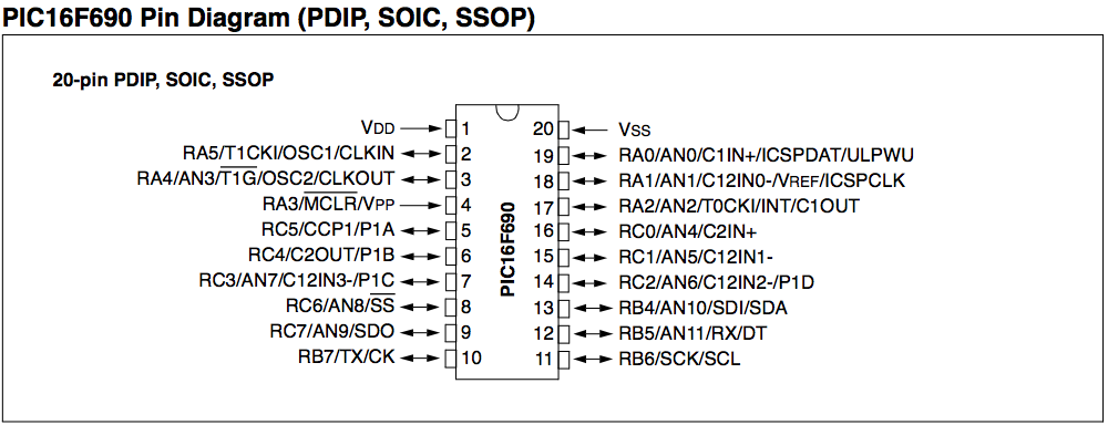
Let us select the pin 16, RC0, to which we want to connect an LED to.
Our code will look like this:
PIC P16F690;
Main {
    digital_output RC0;
    write RC0, 1;
}
That’s it !
Just two lines to light up an LED. And, the code is easy to comprehend.
- There is no need for the developer to know which registers to manipulate for switching a pin to digital output or input.
- There is no need to know how to manipulate certain output registers to write values to a pin.
- All you need to know are the names of the pins which you can get from the pin diagram in the MCU’s data sheet.
Understanding The Code
Let us go over each line of the above code to see what they mean.
PIC P16F690;This is the one-line header that defines which PIC® MCU this program is targeting. It tells the VIC™ compiler to verify the pin names that the user has used in the code, inform the user if they are wrong and generate custom assembly code for that specific MCU.
Main {This is the beginning of the main block of code that will be executed by the MCU. This is a requirement. You will have to create a
Mainblock.digital_output RC0;The above describes a way for setting pin
RC0of the P16F690 MCU as a digital output. The way MCUs are designed today, each pin can be used as a digital or analog I/O port at any point of time in the code. Hence, we have an explicit function to set it. This function will generate the appropriate assembly instructions to setRC0as a digital output port.write RC0, 1;This is a very important line. The
writefunction can do various things. However, in this scenario, we use it to write the value 1 to the pinRC0. Assuming the LED is connected toRC0, this will set the pin output to 1 and the LED will turn on.}The
}here denotes the end of theMainblock. There is no semi-colon needed at the end of a block.
For more details on the language syntax descriptions look at the section on syntax.
Simulating the Hello World! program
VIC™ also supports simulation of the code. As of version 0.23, only
gpsim is supported as a simulator. However, more simulators may be added in
the future.
To add a simulation code in VIC™, we add a block titled Simulator as
below. This block has to be added after the Main block in the source file.
Simulator {
    attach_led RC0;
    stop_after 1s;
    log RC0;
    logfile "helloworld.lxt";
    scope RC0;
}
Let us look at the above code and analyse what we are doing.
Simulator {This line starts the simulator code block.
attach_led RC0;This line calls the
attach_ledfunction to attach an LED to the pinRC0in the simulator.stop_after 1s;This line informs the simulator to stop the simulation after the number of simulated cycles has reached 1 second. Generally, if each instruction cycle takes 1 microsecond to run, then there will be 1 million cycles run by the simulator before it stops.
log RC0;This line turns on logging of the pin
RC0. There are various types of logging options and the default logging is to a text file.logfile “helloworld.lxt”;This line tells the simulator that the logging has to be done in an
LXTformat for thegtkwaveapplication to use. The file name that the logging will be done to ishelloworld.lxt, which can then display the waveforms of the digital outputs usinggtkwave.scope RC0;If the simulator supports displaying a scope, this will show the output pin
RC0on the simulator’s scope view. This may or may not be necessary if the user is using theLXTfile logging option.The scope window in
gpsimis not very sophisticated, but it does a good job of real time plotting. For detailed offline analysis, use the logging mechanism withLXTfiles andgtkwave.}The
}is always used to close an open block as described in the previous section.
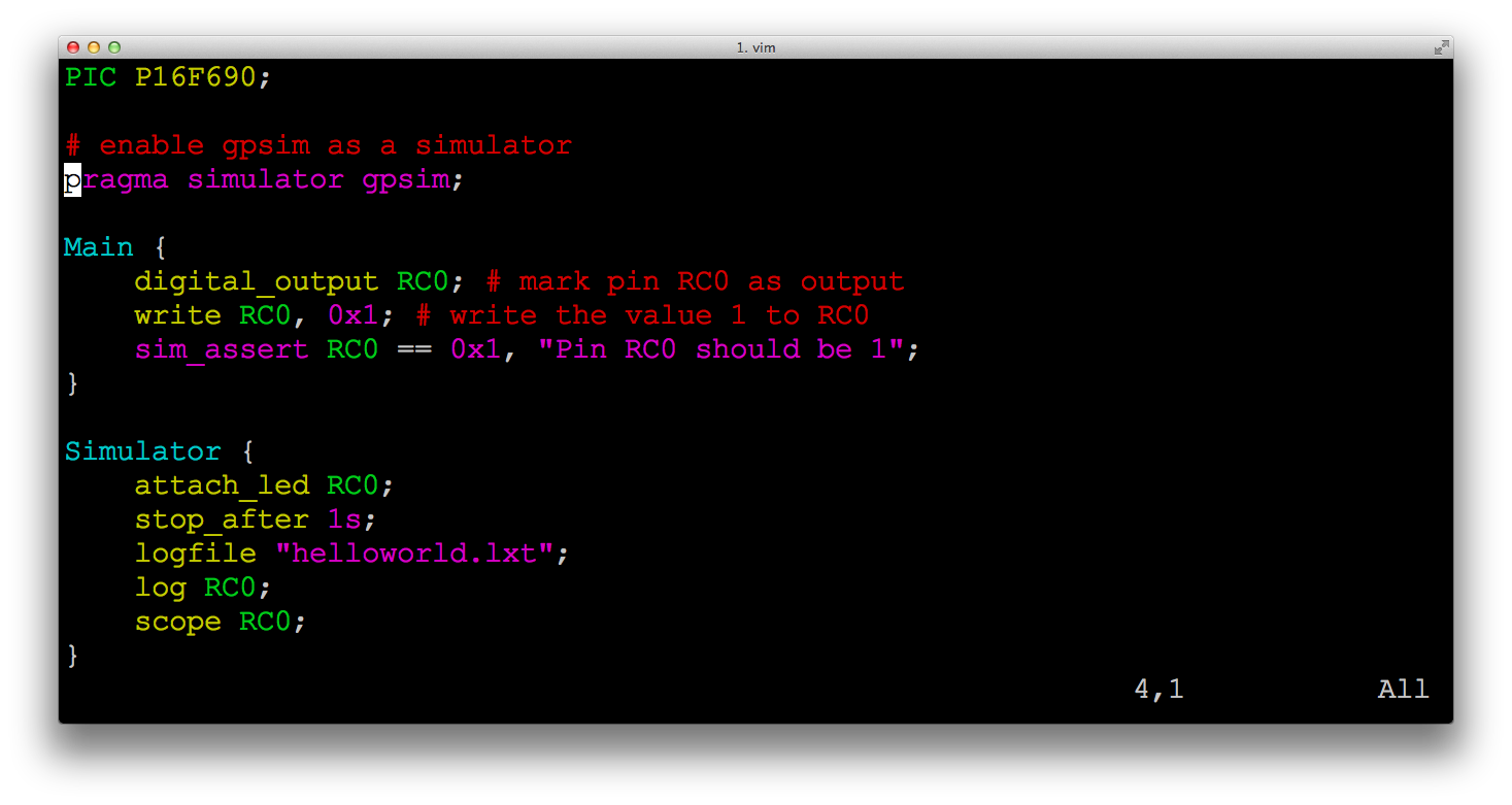
Saving code as helloworld.vic
Let us save both the above code snippets - the Main block and the Simulator
block into a file called helloworld.vic.
PIC P16F690;
Main {
    digital_output RC0;
    write RC0, 1;
}
Simulator {
    attach_led RC0;
    stop_after 1s;
    log RC0;
    logfile "helloworld.lxt";
    scope RC0;
}
helloworld.vic in a TerminalBuilding the code
Compiling VIC™ code is really easy. To compile the file helloworld.vic we run
the following command:
$ vic helloworld.vic -o helloworld.hex
This creates the PIC® assembly file helloworld.asm that is then linked to form the
helloworld.hex file that the user can then use to program the MCU using
pk2cmd or a similar tool. The vic compiler internally finds the installed
gpsim and gplink to perform the assembling and linking to create the .hex
file so the user does not have to do it.
If the user just wants to compile the .asm file they can do the following:
$ vic helloworld.vic -o helloworld.asm
or
$ vic helloworld.vic -o helloworld.hex --no-hex
Then the user compiles this helloworld.asm the standard way using gputils.
$ gpasm -o helloworld.o helloworld.asm
$ gplink -m -o helloworld.hex helloworld.o
A sample make file is provided in the source code path
share/examples/GNUmakefile for the user to take advantage of. The makefile is very
generic and the user can just use it for their own VIC™ code. It compiles
any file present in the same directory that has the extension .vic.
Running the Simulator code
When compiling with gputils a file with the extension .cod is generated. If
you’re using the GNUmakefile to compile the code, then a file .stc is also
generated.
The contents of helloworld.stc are pretty simple.
$ cat helloworld.stc
load s helloworld.cod
The user can manually create this file as well.
This file can be loaded in gpsim using the command:
$ gpsim helloworld.stc
This will load the helloworld.cod file into the gpsim memory and it is ready to
run. However, the user has to type the run command in gpsim to do that.
gpsim> run
This will start the simulator run and the user can then view the LED being lit.
Another way to auto-start the simulation is to have the following contents in
the helloworld.stc file. This can avoid the manual run invocation in
gpsim.
$ cat helloworld.stc
load s helloworld.cod
run
This file can then be loaded in gpsim using the command:
$ gpsim helloworld.stc
Depending on the task being simulated, you may or may not want an auto-started simulation.
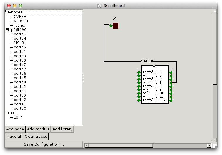
gpsim before run
gpsim after runRunning the code on the PIC® itself
For the PICKit 2 Starter Kit, there is an open source software called
pk2cmd
that can be used on Linux and Mac OS X to copy the .hex file generated onto the
MCU using PICKit 2 Starter Kit. We have not tried with the PICKit 3 Starter Kit, but the user can
experiment with Microchip’s IDE or Piklab to perform the writing.
The user can also combine the code generated by VIC™ with Microchip’s IDE or Piklab, and use
it that way instead of using gputils. However, we do not support Microchip’s
simulator yet as part of VIC™. We may choose to do it in the future.
Vikas N Kumar (@vikasnkumar) is the author of VIC™. All copyrights belong to the author and Selective Intellect LLC.
VIC™ is licensed under the license terms of Perl.
The development of VIC™ is sponsored by Selective Intellect LLC.
This page was last updated on 2014-12-02 10:39:14 -0500.